Introduction
In this chapter we will tackle about some techniques that is commonly applied in circuit design and analysis. These techniques includes combining resistors in series or parallel, voltage division, current division and delta-to-wye and wye-to-delta transformations.
Ohm's Law
To make a current flow through a resistance there must be a voltage across that resistance. Ohm's Law shows the relationship between the voltage (V), current (I) and resistance (R). It can be written in three ways:
V = I × R or I = V or R = V
R I
where:
V = voltage in volts (V)
I = current in amps (A)
R = resistance in ohms (Ω)
or:
V = voltage in volts (V)
I = current in milliamps (mA)
R = resistance in kilohms (kΩ)
For most electronic circuits the amp is too large and the ohm is too small, so we often measure current in milliamps (mA) and resistance in kilohms (kΩ). 1 mA = 0.001 A and 1 kΩ = 1000Ω.
The Ohm's Law equations work if you use V, A and Ω, or if you use V, mA and kΩ. You must not mix these sets of units in the equations so you may need to convert between mA and A or kΩ and Ω.
A node is an uninterrupted segment of wire of any shape. Unless otherwise stated, the wire is considered to be perfect and have no resistance. Therefore, all points on the node have the same voltage. Physically speaking, a node may connect components inches away. However, electrically speaking all the components are connected to a single point. In a schematic representation, node1 extends from the top terminal of the 120V source to the left terminal of the 33 ohm resistor. Node2 includes all the wire segments between R1, R2 and R4. No matter how long the lines extend between components, no potential difference exists between them as long as they are on the same node. A branch is any element connected between two nodes. R4 and R3 are examples of a branch. A loop is any sequence of elements connected between nodes that starts and ends at the same node. You only include a node once in a loop. There may be loops within loops as loop1 and loop2 are within loop3.

Kirchhoff's Law
The voltage across each element and the current through each element in an electric circuit are governed by two general results which are summarized in Kirchhoff's two laws. Since Kirchhoff's laws are derived from general physical properties of electricity, they are applicable to all kinds of electric circuits.
Kirchhoff's Current Law
As a direct consequence of the conservation of charge, namely charge can neither be created nor destroyed, the node, being of negligible physical size, holds no charge. For instance, referring to figure 1.6, the sum of
 ,
,  and
and  must equal zero.
Figure 1.6: Kirchhoff's current law
Formally, KCL states that the algebraic sum of the currents in all the branches that converge in a common node is equal to zero. In mathematical form, for n branches converging into a node, KCL states that
 where
where  is the current flowing in the kth branch and its direction is assumed to be pointing towards the node.
Kirchhoff's Voltage Law
When a charged particle is moved from a point to another, the work done is
 , where V is the voltage across the two points and
  is the amount of charge on the particle. Consider a particular case where the two points are actually the same point in the circuit. In this case, the work done is zero. By the same argument, if a unit charge is moved around a closed path such as the square path shown in figure 1.7, the work done is zero, i.e.,
Figure 1.7: Kirchhoff's voltage law
Formally, KVL states that the algebraic sum of the voltages between successive nodes in a closed path in a circuit is equal to zero. In mathematical form, for a closed path with successive nodes
 , KVL states that
 where
where  is the voltage between nodes j and k.
The Voltage Divider
For a single resistor with a voltage across it, Ohm's Law is quite an impressive tool. Put a few resistors together in series, however, and things get even more interesting! The total resistance of resistors in series is simply the sum of their individual resistances. By combining this concept with Ohm's Law we can design one of the most commonly used circuits in a guitar amplifier: the voltage divider.
Problem
Consider the power supply of a Mesa Boogie Bass 400 amplifier. It uses two 150k resistors in series to equalize the voltage across the filter capacitors and to act as bleed resistors that slowly discharge the capacitors when the amplifier is turned off. (If only all amplifiers were designed this way - it would be a much safer world!) The total voltage across both resistors is 534 volts. What is the voltage across each individual resistor?

Solution
The total resistance across both resistors is
150k + 150k = 300k
According to Ohm's Law, the current passing through the resistors is
534/300k = 1.78mA
Thus 1.78mA passes through each of the resistors individually. By applying Ohm's Law once more, we get the voltage across one resistor:
(1.78mA)(150k) = 267V
The Voltage Divider
A voltage divider is often used to attenuate a signal by a prescribed amount. We often see them in guitar amplifier input circuits, for example, where they attenuate the signal to give the guitar player a low-gain input jack. They are also used in the second stage of a paraphase inverter to equalize the amplitudes of the two output phases. Other guitar circuits may not appear to be voltage dividers at first, but we frequently discover that at certain frequencies the components effectively create one. The voltage divider thus represents an essential tool of guitar amplifier design.
Problem
Consider the second stage paraphase inverter of the Gibson GA-20T amplifier. An input signal is applied across 220k and 4.7k resistors in series. The output voltage is the voltage across the 4.7k resistor. Given that the input signal is 1 volt, what is the output voltage?

Solution
The total resistance of both resistors in series is 224.7k. This means that according to Ohm's Law the current is
1/224.7k = 0.00445mA
This current passes through the 4.7k resistor, so according to Ohm's Law, the voltage across it is
(0.00445mA)(4.7k) = 0.021
So the input is 1 volt and the output is 0.021 volts. The output is thus only 2.1 percent of the input. This is quite a bit of attenuation and not a random value picked by the engineers in Kalamazoo. The resistor values were chosen to reduce the input voltage by exactly this amount.
Notice that we computed the output voltage in two separate steps. First we computed the current that passes through both resistors. Then we used this current to determine the output voltage. We really weren't interested in the current. We just needed it as an intermediate step. Let's avoid the middleman and combine the two steps into one equation to simplify the calculation. Looking at our procedures in reverse, the output voltage is
(0.0445mA)(4.7k) = 0.21
and the current is
1/224.7k = 0.0445mA
We combine these into a single equation by noting that the 0.0445mA in the first formula is equal to 1/224.7k in the second. Thus
(1/224.7k)(4.7k) = 0.021
So the output voltage is equal to the input voltage divided by the total resistance in series, times the resistance across the output. This works for any combination of two resistors R1 and R2, as shown in this circuit:

The output voltage is equal to the input voltage times the output resistor R2 divided by the total resistance R1+R2. This is the fundamental Principle of a voltage divider.

Current Division

Consider the circuit shown in figure where two resistors are connected parallel. Supplying voltage for current resistor. From Ohm’s law we get
v = i1R1
= i2R2
or i1 = V/R1, i2 = V/R2
Applying KCL,
i = i1 + i2
Substituting and adding the value in equation (i) then we get,
i = V/R1+ V/R2
= V (1/R1 + 1/R2)
= V/Req
Here Req is the equivalent resistance.
1/Req = (1/R1) + (1/R2)
Or 1/Req = (R1 + R2)/ R1 R2
Req = R1 R2/ (R1 + R2)
Using current divider rule,
I1= R2i/ (R1 + R2)
I2= R1i/ (R1 + R2)
Wye-Delta Transformations
Most of the time we can solve the circuit using our idea of series and parallel connection and ohm’s law or KCL or KVL. But sometimes we encounter some circuit where the formations of elements are neither in series nor in parallel. For example look at the figure of bridge network below:

Now look at the following two formations which look like Wye and Delta. These formations usually found in three phase connections, filters, or in matching networks.

(a) Y netwrk (b) Delta Network

(a) Delta Network

(b) Pie Network
When we analyze a circuit we may find a certain formation to be helpful. And we might want to change one formation into other. Suppose it might helpful for us to work with Wye formation in three phase rather in Delta formation. So we have to know how to transform a Delta network into Wye network.
Delta to Wye conversion:
Look at the figure below:
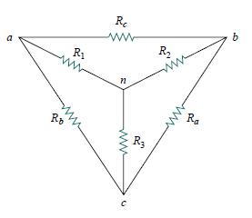
Now for Delta to Wye conversion:
R1 = (Rb . Rc) / (Ra + Rb + Rc)
R2 = (Rc . Ra) / (Ra + Rb + Rc)
R3 = (Ra . Rb) / (Ra + Rb + Rc)
We don’t have to memorize these formulas rather we can easily remember these.Each resistor of the Wye network is the product of the two adjacent resistors of Delta network, divided by the sum of all three resistors of the Delta network.
Wye to Delta Conversion:
Look at the figure again:
Now for Wye to Delta conversion:
Ra = (R1.R2 + R2.R3 + R3.R1) / R1
Rb = (R1.R2 + R2.R3 + R3.R1) / R2
Rc = (R1.R2 + R2.R3 + R3.R1) / R3
We don’t have to memorize this also. The easy way to remember is, each resistor in the Delta Network is the sum of all possible product formation of Wye network’s resistors taken two at a time, divided by the opposite Wye resistor.